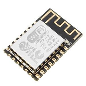
 SMS4IOT for ESP8266 2.4GHz - beta
TL;DR HowTo
- Write firware into esp8266
- Download latest esp8266 firmware
(
sha256sum e893574.bin 37796d9b4f5b756ee854be5118fa545bb6718f9e3b57d92ee2a9fe1524de98f6
) and upload to esp8266 module. If you are looking at this page, I expect you already know how to do this.
- Follow the rtl8720dn instructions for the rest
- Firmware notes:
- GPIO_0 button to gnd that toggles relay and generates a QR code on serial console for the mobile app to scan. Also tries to generate QR on SSD1306 display if attached.
- GPIO_2 output controlled by sending text to device "setrelay on" or "setrelay off". Shown as ON or OFF.
- GPIO_13 input sensing logic level and shown as H (high) or L (low)
- ADC0 is analog input to ADC and ranges from 0 to 3300mV
- GPIO_5 = SCL and GPIO_4 = SDA. If you connect a SSD1306 128x64 I2C display to these pins, the firware will automatically detect it at boot and display text you sent from the app on it as well as ID and currently used hotspot name.
- GPIO_15 blue led to indicate connection status
- GPIO_12 red led to indicate relay status
- If the hotspot being used is completely open, such as one in your laboratory or your controled environment, the firmware will look for an updated version and start downloading it automatically. Version can be displayed with "set" command and at device boot if SSD1306 display is attached.
Patented. Copyright 2022-2023 Department C Inc.
ftc9ky

